The Role of an Elevation Plan in Construction
- Oct 6
- 4 min read
In construction, turning a vision into reality requires careful planning, measurements, and execution. Every construction project depends on detailed drawings that guide architects, builders, and engineers, and out of them, the Elevation Plan happens to be the most important thing.
What is an Elevation Plan?
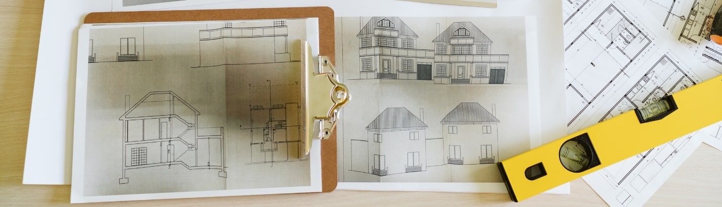
An elevation plan is basically a drawing that shows the external face of a building. It shows each side of the structure in a scaled, two-dimensional view. Details such as wall height, window placement, roof slope, and decorative features are all represented.
So unlike a floor plan, which maps the layout of spaces horizontally, or a reflected ceiling plan, which illustrates the arrangement of overhead elements, an elevation drawing focuses on vertical surfaces and exterior design. In some cases, it may also depict interior elevations for walls within specific rooms. This makes it one of the most reliable ways to visualize the finished look of a building, even before the construction process starts.
What is the importance of an elevation plan?
An elevation plan drawing plays an important role at every stage of a construction project. Some of the key advantages of this thing include:
Simplifying construction
The drawing acts as a clear reference for builders. Since it shows exterior dimensions and finishes, it reduces confusion and makes on-site execution more accurate.
Supporting maintenance
Homeowners often rely on these drawings for future upkeep. Having a record of the building’s exterior helps in identifying areas that may need repair, repainting, or upgrades.
Reducing waste of resources
Miscommunication in design can lead to expensive rework. Elevation drawings give clarity upfront, preventing avoidable errors and saving both time and money.
Making changes easier
If the building requires adjustments such as a new balcony, altered roofline, or repositioned windows, builders can refer to the plan to implement consistent modifications.
Planning accessibility
Elevation drawings also take surrounding elements into account. Existing features like trees,
retaining walls, or site slopes are included, helping stakeholders anticipate possible constraints on movement or construction.
What are the main Components of an Elevation Drawing?
To be accurate and useful, an elevation drawing must capture a range of details such as:
Architectural features: Facade treatments, finishes, trims, and decorative details that define the building’s style.
Dimensions: Measured data that shows the size of walls, doors, and other external elements.
Scale: Drawings are prepared to scale so that proportions and distances are clear.
Windows and doors: Placement, size, and type of openings are clearly marked.
Roof details: The slope, pitch, and any additional features like chimneys or skylights.
Vertical heights: Information on floor-to-floor measurements and the overall height of the building.
Material notes: Specifications of construction materials for exterior finishes.
Landscaping elements: Pathways, fences, or gardens may also be included to give context to the overall design.
Together, these elements ensure that everyone involved in the project, like the designers, contractors, and owners, has the same understanding of the building’s final look.
Types of Elevations
When preparing an elevation plan drawing, architects provide four views to cover all directions:
North Elevation – The building’s face is oriented toward the north.
South Elevation – The opposite view.
East Elevation – The eastern side of the structure.
West Elevation – The western view.
These four types of elevations provide a complete picture of the building from every direction. Depending on the project’s complexity, additional interior or sectional elevations may also be prepared as needed.
How is an Elevation Plan Drawing done?
Creating an elevation plan involves a series of precise steps. While digital tools are now common, the logic behind the process remains the same:
Draw the baseline
Start off with the baseline of the ground floor walls, using the floor plan as a reference. Include wall thickness and exterior finishes.
Set wall heights
Establish vertical lines that indicate wall height. These are calculated by considering ceiling levels, slab thickness, and joist dimensions.
Add doors and windows.
Place openings in their exact positions. Dimensions are taken from a separate schedule for accuracy.
Draw the roof
Include the chosen roof style, such as gable, hip, shed, or gambrel, along with overhangs and slopes.
Include decks and railings.
Add balconies, porches, stairs, or external decks with correct measurements.
Review with stakeholders
Share the draft with the client and project team for feedback. Any corrections are incorporated at this stage.
Final approval
The drawing is finalised once it meets design expectations, local codes, and client requirements.
The success of the process of a home building project heavily depends on clarity at the design stage. An elevation plan provides this clarity by presenting a scaled and detailed picture of the building’s exterior and also assists in construction, supports future maintenance, and ensures efficient use of resources. Alongside floor plans and reflected ceiling plans, it forms the foundation of accurate and effective building design.

Cookies help us display personalized product recommendations and ensure you have a great experience.
Accept Cookies